
Support Faqs
Return to: Support
![]() Questions about sound masking system installation or commissioning?
Questions about sound masking system installation or commissioning?
Get the answers to the support based questions our team members are most often asked.
Download the QtPro® System Layout Guidelines for Standard Qt® Emitters
How many emitters can I have per run? Per zone?
For our standard (passive) emitter products, A single run (one daisy chain from the control module) can have 60 emitters or, 1,000 feet (305 m) of cable, whichever comes first. The number of runs per zone is dependent on the type of control module.
For our active emitter products, these require the addition of our PS-AE-3 Qt® Active Emitter Power Supply (3-Zone Power Supply) and the PI-AE Qt® Active Emitter Power Injector (which combines power & the audio signal to each string of emitters. The PI- AE Only powers a maximum of 50 emitters on the same Zone (with 25 emitters on Output 1, and 25 emitters on Output 2) A combined Powered Cable + Signal Cable Must be Less than 1,000 feet per run (i.e. a combination of the 14 AWG cable from the PS-AE-3 Power Supply to the PI-AE (Injector) at 400 feet Maximum, then *Up to 400 feet of Powered Signal Cable (CATx) *Per Output “Post Injector” of the PI-AE maximum.
Is there a limit to the amount of cable I can use?
For our standard (passive) emitter products, a single run (one daisy chain from the control module) cannot have over 1,000 feet (305 m) of cable between the first and last emitter in a run. This is due to the limitations of CAT cabling, over 1,000 feet (305 m) of cable will result in over a decibel in volume drop between the first and last emitter of the run. There is not a limit to the length of cable between two emitters, as long as the overall run stays under 1,000 feet (305 m), It is not recommended to use a large number of custom length cables.
For our active emitter products, a combined Powered Cable + Signal Cable Must be Less than 1,000 feet per run (i.e. a combination of the 14 AWG cable from the PS-AE-3 Power Supply to the PI-AE (Injector) at 400 feet Maximum, then *Up to 400 feet of Powered Signal Cable (CATx) *Per Output “Post Injector” of the PI-AE maximum.
How do I zone the system?
If you have an installation or bid plan, follow the zoning outlined. If none is provided, in general, it is recommended to zone open office areas separately from enclosed spaces or hallways, as they have very different acoustics. Sections of open plan with different ceiling heights may have to be zoned separately as well, depending on ceiling height, to allow the speakers to sound the same at ear level. Detailed instructions can be found in the System Planning and Layout Guidelines.
I have ceilings over 12ft/3.6m. What grid spacing should I use?
If the ceiling height is over 12 feet (3.6 m), it is still recommended to keep the emitters on a 12 feet (3.6 m) grid. This allows the system to still have enough sound energy at ear level without having to push the upper limits of the volume settings. If the ceiling is over 25 feet (7.6 m), discuss the project with our design team.
How does the layout differ in a private office?
Private offices have different acoustics than open plan, therefore they have different rules. Measure the area of the office and compare to the private office area chart in the System Planning and Layout Guidelines to determine the number of emitters needed and the recommended layout.
Why do I need at least 2 emitters in a private office?
This creates the most uniform sound. If there is just one emitter in a small space, the occupant is more likely to be able to easily distinguish where the sound is coming from. By positioning two emitters in a private office (more for larger offices), the sound source becomes indistinguishable. Uniform sound coverage is essential for a comfortable workspace.
I don’t have a furniture plan. How do I know where the occupant is sitting in an enclosed office?
The desk tends to be in the opposite corner from the door. However, there is usually enough service loop to allow reconfiguration of emitters after the desk location is known.
Do I need to connect the cabling in a certain order?
Yes. It is very important to pay attention to the inputs and outputs of the emitter as you install the system. The cable coming from the previous emitter should go into the input, and the cable going to the next emitterinto the output. Additionally, if you have been provided a wiring diagram, follow the wiring pattern shown. If you do not have a wiring diagram, follow a serpentine pattern in the open office areas. For private offices, just connect all the emitters in one room before moving on to the next. Detailed instructions can be found in the System Planning and Layout Guidelines.
I can’t install the speaker exactly where it is shown on the plan. Can I move it?
Yes, emitters can be moved up to 2 feet (60 cm) in any direction to accommodate existing features in the space. Detailed instructions can be found in the System Planning and Layout Guidelines.
What volume level should I set the masking to for each zone?
The volume range on Qt® control modules are in 1 dB increments and the Oasis Qt module is in 3 dB steps. The recommended volume setting is dependent on the type of space the zone covers. Open office areas should fall between 45-48 dBA and private offices 38-42 dBA. It is recommended to use a sound level meter to set the volume. If the installer does not have access to a sound level meter, each control module has recommended volume settings listed in their installation guide.
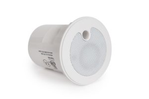
I need more granular adjustment for a emitter. What are my options?
Use Qt® Adjustable Emitters to add granularity when needed during or after installations. These emitters allow users to reduce the volume level of an individual emitter by up to 9 dB in 3 dB decrements. The adjustable emitter is appropriate for individual spot adjustments, or creating micro zones down to 100 square feet (9.3 m2) of space.
How do I install the Universal Bracket?
Mounting to a wooden beam or the wall (most common):
1. Separate the cylinder and bracket. Remove ring from back of emitter. Discard the ring.
2. Slide the emitter into the cylinder and turn clockwise to lock in place. (If the emitter doesn’t turn easily, remove the emitter, rotate it 180 degrees and repeat.)
3. Snake the input and output cables with RJ-45 connectors through the two larger holes on the bracket.
4. Secure the bracket to the beam or wall using screws (and hollow wall inserts if necessary) in the small outer holes.
5. Connect the input and output cables to the appropriate RJ-45 jacks on the back of the emitter.
6. Finally, connect the cylinder to the bracket at the desired angle – either pointing directly down or angled into the workspace.
Hanging from cement, metal, grated or other unusual ceilings:
**NOTE: this requires purchasing a ¼ inch-20 threaded rod**
1. Purchase a ¼ inch -20 threaded rod from a local hardware store. These come in various lengths from 2 feet (0.6 m) to over 20 feet (6 m). Depending on the installation, you may also need a wall insert anchor.
2. Separate the cylinder and bracket. Remove ring from back of emitter. Discard the ring.
3. Slide the emitter into the cylinder and turn clockwise to lock in place. (If the emitter doesn’t turn easily, remove the emitter, rotate it 180 degrees and repeat.)
4. Attach the rod to the ceiling using a threaded rod anchor and/or drywall anchor. Be sure the threaded end is pointing down into the space
5. Attach the threaded end of the rod to the small hole in center of bracket. Turn clockwise until tight.
6. Snake the input and output cables with RJ-45 connectors through the two larger holes on the bracket.
7. Connect the input and output cables to the appropriate RJ-45 jacks on the back of the emitter.
8. Finally, connect the cylinder to the bracket at the desired angle– either pointing down or angled into the space.
How do I install the Beam Bracket?
1. Use smaller screw to attach beam clamp to the cylinder.
2. Slide the emitter into the cylinder and turn clockwise to lock in place. (If the emitter doesn’t turn easily, remove the emitter, rotate it 180 degrees and repeat.)
3. Use larger screw to secure entire unit to the I-beam or conduit.
4. Finally, connect the input and output cables to the appropriate RJ-45 jacks on the back of the emitter
How do I install the Drywall Mount?
1. Drill a 3” (76 mm) diameter hole into drywall ceiling at emitter location.
2. Insert springs into mount. Thread curved end of each metal spring through the top hole, keeping the lip of the spring flush with the outside of the housing. Push flat end of the spring into the bottom hole, ensuring that the springs are not in lock position.
3. Slide emitter mount, with spring in place into the pre-drilled 3”/76mm hole.
4. Once mount is flush with the drywall, push springs out so that they are locked in place.
5. Connect the input and output cables to the emitter.
6. Place emitter into the mount. Use the provided installation key and turn clockwise to secure emitter in place.
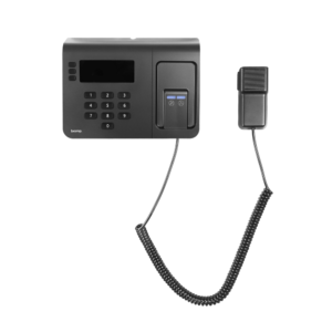
I want to page with my masking system. What do I need?
All Qt® control modules have audio inputs built in for use with a paging source. These audio inputs do have particular input requirements, so it is critical you check that your source matches these. First, determine what you will use for the source of your page, and find out what type of signal out it supplies. Our systems require a dry (no dial tone, no ringer voltage, no DC), line-level (US Pro Audio line-level) signal in. If your source does not match this requirement, you may need additional equipment between the paging source and the Qt control module. Pre-amps can be used with paging microphones to bring mic-level signals up to line-level. Paging controllers can be used to connect to phone system fxo/fxs ports and provide a dry signal to the control module. Please see technical specs for each control module for more detail on the input requirements.
Can I control the aux audio volume independently in each zone?
Yes, each zone has independent volume control for masking and each external audio source. These can also be muted.
Will the masking mute when I play paging or music?
No, the system does not override one signal with another. They play out simultaneously, unless it is set to mute on that zone.
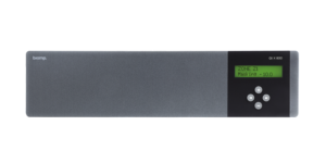
I can’t scroll through the screens on my Qt® control module. What’s wrong?
The panel lock switch is likely in the lock position to prevent unauthorized access. On the Qt® 300 and Qt® 600, this is on the back of the unit next to the contact closure phoenix connector.
One of the emitters is not working.
There is likely a problem with one of the input or output connections. Ensure that both cables are firmly plugged into that emitter. If this does not solve the problem, the issue likely exists within the previous 4 emitters (because of the 4-channel system). Check the input and output cable connections on each of the 4 previous emitters on the chain. This will solve the problem 95% of the time.
If the problem persists, there is likely a faulty cable. Use a cable tester to verify that the cables are working correctly. Replace cables as necessary.
My control module keeps losing its volume settings. Why?
Qt® control softwarerequires user to press submit after making changes. Additionally, make sure that you do not have any buttons pressed on the unit while powering up your Qt control module as that can erase settings.
My control module says ‘Status: Error’. What do I do?
If you are viewing the front panel, press the right arrow once to view the error code. Compare the error code on the front screen with the Operations Guide. Find the cause of the error and resolve. Press “+” to acknowledge and clear the error. If you are viewing the error on the software, click the error link to generate a pop up describing the error. Find the cause and resolve. Press ‘acknowledge’ to clear the error.
My control module front panel says ‘Warning Time Ops’. What does this mean?
This indicates that the system has different volume settings for day and night in the software. The warning is in place because if you change the volume via the front panel, it will override both and change both to the new setting. It will no longer ramp for time of day. To maintain ramping, make all volume changes via the software.
My paging and music system does not seem to be working.
First, check to make sure your sound masking control module is turned on. Even if you are not using sound masking in the space, the module must be powered ON (even if at the lowest volume) for the paging and/or music system to function.
If the problem persists, confirm that your system is wired properly. See the module’s Installation guide for details.
How do I access the software?
Connect the control module to a router or corporate network You can access the software from any computer connected to the router or network. Users can also connect the control module directly to a computer.
1. Read the IP address (or hostname) from the control modules front panel. Bring up a browser.
2. Type the IP address (or hostname) into the web browser (default hostname is on the front panel)
3. Type in the user name and password (found on front panel). The default user name is ‘admin’ and password is ‘secret’. Both are case sensitive.
4. If you need to access the equalizers, you would enter the higher level password (obtained from CSM) instead of the basic password. User name stays the same.
Can I use any browser to access the software?
Yes, any browser will load the software. Google Chrome does not work with the hostname; it will search the hostname instead of checking to see if an IP address is associated with it.